This allows you to output touch coordinates to a PC using serial communication. To use the PC mouse cursor to emulate touches on the display unit, install on the PC mouse emulation software so the PC can receive touch information sent from the display unit.
For the touch output, have the following ready.
Mouse emulation software manufactured by Digital Electronics Corporation of Japan.
USB communication driver (for RGB Units only) manufactured by Digital Electronics Corporation of Japan
(This software can be downloaded from the support site "Otasuke Pro!"
(http://www.pro-face.com/otasuke/).
USB communication driver can be installed from the CD included in the RGB unit.)
RGB cable (optional or commercially available)
Serial cable, cross (commercially available): VM Unit, DVI Unit
USB cable (optional or commercially available): RGB Unit
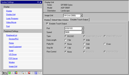
Emulate Touch Output
Using RGB inputs, select whether or not to output touch coordinates to external devices over serial communication lines.
Port
Select a port for the touch output from [COM1], [COM2] or [USB-SIO].
When specifying the port number to be used, mark ("Duplicate Port") is displayed.
Transmission Speed
Select a communication speed from [2400], [4800], [9600], [19200], [38400], [57600] or [115200].
Communication Settings
Select the communication method from [RS232C], [RS422/485 (2wire)], or [RS422/485 (4wire)].
Data Length
Choose the data length from [7 bit] or [8 bit].
Parity
Select the parity bit from [None], [Odd], or [Even].
Stop Bit
Select the stop bit from either [1] or [2].
Flow Control
Select the flow control from [None], [RTS/CTS], or [ER (DTR/CTS)].
When [USB/SIO] is selected in [Port], the setting becomes [None].
Setup Procedure
In the system settings window, select the [Emulate Touch Output] check box in the [Image Unit Setting] to configure the communication settings. Configure the mouse emulation settings on the PC.
From the [Common Settings] menu select [Image Unit Window Settings] and create a new screen. Double-click the displayed screen and open the Settings dialog box. In the [Channel] list, select [RGB(IN)] and select the [Touch Output] check box.
Draw the Image Unit display on the base screen and set up the window display settings.
Operation Method
Write "1" in the display unit's internal device address LS9230 to enable touch output. The touch information to be output will be written in LS9231 - LS9233.
LS9230 |
Allowed/Not allowed |
0: Not allowed, 1: Allowed |
LS9231 |
Touch State |
0: Touch ON 1: Touch OFF |
LS9232 |
X: |
0 to 1023 |
LS9233 |
Y: |
0 to 1023 |
When displaying two channels simultaneously on an RGB unit, touch information is written into the following areas.
Channel 0 Touch Information |
||
LS9350 |
Touch State |
0: Touch ON 1: Touch OFF |
LS9351 |
X: |
0 to 1023 |
LS9352 |
Y: |
0 to 1023 |
Channel 1 Touch Information |
||
LS9353 |
Touch State |
0: Touch ON 1: Touch OFF |
LS9354 |
X: |
0 to 1023 |
LS9355 |
Y: |
0 to 1023 |