![]()
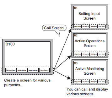
If you set the screen's background color used for a call screen, the objects placed on the screen are not displayed on the display unit.
A maximum of 10 nesting levels (11 layers) can be set for Call Screens.
For example, 2 nesting levels (3 layers) 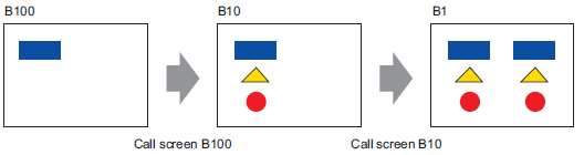
While creating the project, if the computer memory capacity gets low, and the screen is set up with multiple levels of call screens, the nested screens may not appear on the editor. However, once transferred to the display unit, they will display properly.
From the [Screen (S)] menu, select [New Screen (N)]. The following [New Screen] dialog box will appear. Click [New] to create a new base screen. (For example, Base Screen 2)
From the [Draw (D)] menu, select [Call Screen (O)] or click ![]() .
.
When drag onto the created screen, a dashed line displays and the [Call Screen] dialog box appears.
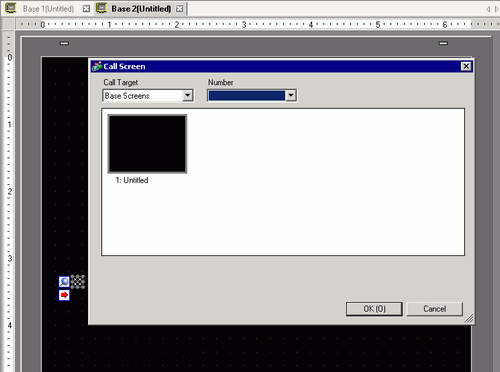
Select the target image from [Call Target].
Base Screen
Previously created base screens will display.
Image (Display Unit)
The image data registered in "Image Registration" will display.
Image (CF)
The CF-card image data registered in "Image Registration" will display.
Mark Registration
Displays registered marks in "Mark Registration".
Keypad
The keypads registered in "Keypad Registration" will display.
![]()
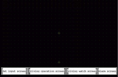
When you call a [Base Screen], call and place it in the center of the screen.
Select an image and click [OK] to display the designated image.
![]()
After drawing a [Call Screen] object, on the top left corner of the object, below the fixed pin, the jump icon becomes available. Click this icon to load the called screen. This feature is convenient for checking and editing screens.