22.8 Trigger Condition Setup
A created script can use any of the following 11 types of trigger conditions.

-
The interval for the trigger bit ON/OFF status or true/false condition must be longer than the communication cycle time*1 or display scan time*2, whichever is longer. See the following for more details.
 22.10.5 Restrictions on the Triggered Bit
-
Selecting [Continuous Action], [While Bit is ON], [While Bit is OFF], [While Condition is True] or [While Condition is False] for the trigger condition could prevent updates on parts and screens.
If a display update does not run properly, use a different trigger condition.
Executes each display scan time.
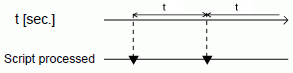
Each time the designated time elapses, the script is executed one time. The timer duration can be set from 1 to 32767 seconds.
-
When setting the timer function's time, the time value includes the set time + display scan time error. Also, depending on the time taken to draw a screen item or to print out data, the timer function may be slowed.
-
When using D-Script, switching the screen causes the timer function to restart counting from 0.
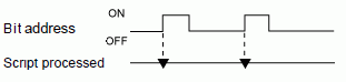
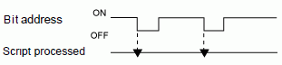
When the display unit detects the designated bit address (trigger bit) rise from 0 to 1, the script is triggered.
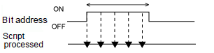
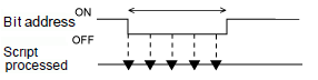
While the designated bit address (trigger bit) is ON, the script is executed at every display scan time.
When the GP detects the designated bit address (trigger bit) fall from 1 to 0, the script is triggered.
While the designated bit address (trigger bit) is OFF, the script is executed at every display scan time.
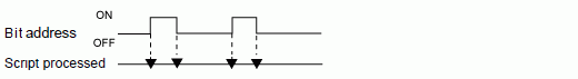
When the GP detects the designated bit address (trigger bit) rise from 0 to 1 or fall from 1 to 0, the script is triggered.
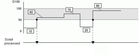
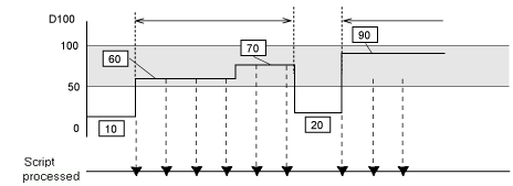
When the defined condition is met, the script runs one time.
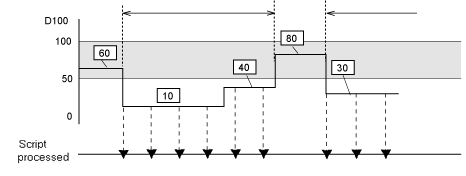
For example: When the Trigger Condition is 100 > [D100] > 50,*3 the script will execute with the following timing.
[False] → [True] is detected, the script executes and 70 is assigned to D100.
The script does not run when [True] → [True] is detected.
While the condition is true, the script is executed at every display scan time.
For example: When the Trigger Condition is 100 > [D100] > 50,*3 the script will execute with the following timing.
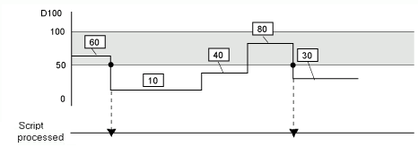
When the defined condition is false, the script runs one time.
For example: When the Trigger Condition is 100 > [D100] > 50,*3 the script will execute with the following timing.
[True] to [False] is detected. The script executes and 40 is assigned to D100.
The script does not run when [False] to [False] is detected.
While the condition is false, the script is executed at every display scan time.
For example: When the Trigger Condition is 100 > [D100] > 50,*3 the script will execute with the following timing.