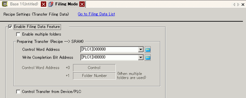
Enable Filing Data Feature
Select to transfer filing data.
Enable Multiple Folders
Select to create multiple folders.
Preparing Transfer (Filing Data -> SRAM)
Control Word Address
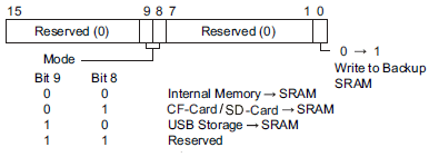
In the backup memory (SRAM), specify the word address to write the recipe to. Turn ON the address's bit 0 to write data to backup memory (SRAM). Use bit 8 and bit 9 to set the transfer operation.
![]()
This address is not turned OFF automatically. After the [Write Completion Bit Address] turns ON, turn OFF bit 0.
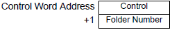
If using multiple folders, you need to specify the folder numbers first. Store the folder number (1 to 8,999) for writing to backup memory (SRAM), then turn ON bit 0 of the control address.
The number of addresses used depends on the device designated in the address.
For example, when 16 bit device is specified
Only one folder can be stored in backup memory (SRAM).
When using the GP-4100 Series (Monochrome Model), you can use bit 0 of the control word address but not bits 1 and up.
Write Completion Bit Address
Set the bit address that verifies when writing data to backup memory (SRAM) is complete. When filing data is stored correctly in backup memory (SRAM), this bit turns ON. After confirming completion, turn OFF this address.
![]()
When recipes cannot transfer to backup memory (SRAM), for example due to insufficient memory or control address bits 8 and 9 are turned ON, bit 9 of the display unit's internal device LS2032 turns ON.
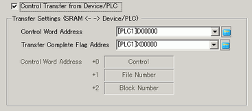
Control Transfer from Device/PLC
Set to control filing data transfer from the device/PLC (automatic transfer).
![]()
For manual transfer, this setting is not required.
Transfer Settings (SRAM <--> Device/PLC)
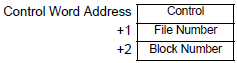
Control Word Address
Set the word address that controls the transfer between backup memory (SRAM) and the device/PLC. The number of addresses used depends on the device designated in the address.
After designating the File Number and Block Number in BIN format, the transfer starts when this address' bit 0 turns ON. The transfer destination is set in bit 8.
![]()
![]()
The number of addresses used depends on the device designated in the address.
For example, when 16 bit device is specified
This address is not turned OFF automatically. After confirming that the [Transfer Complete Flag Address] is ON, turn OFF bit 0.
Transfer Complete Flag Address
Set the bit address that verifies that the data transfer between backup memory (SRAM) and the PLC is complete. When the transfer completes successfully, this bit turns ON. After confirming completion of the transfer, turn OFF this address.
![]()
If data transfer between backup memory (SRAM) and the device/PLC cannot run, the display unit's internal device LS2032 bit 10 turns ON.
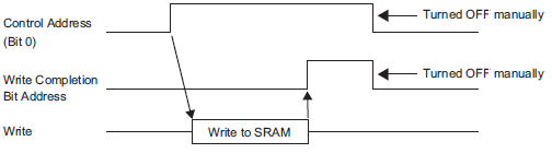
Transfer Preparation Timing Chart
When the [Control Word Address] bit 0 turns ON and filing data is correctly stored in backup memory (SRAM), the [Write Completion Bit Address] turns ON. After confirming completion, turn OFF this address.
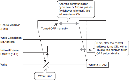
If data cannot be transmitted to backup memory (SRAM) due to insufficient memory, the internal device (Special Relay Area) LS2032 bit 9 turns ON. To transfer data again, turn OFF the [Control Word Address] bit 0 temporarily. Then, after setting the communication cycle time as either your standard communication cycle time or 150ms (whichever is longer), turn it ON.
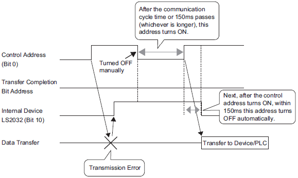
Automatic Transfer Timing Chart
When the designated [Control Word Address] bit 0 turns ON and filing data is correctly transferred, the [Transfer Complete Flag Address] turns ON. After confirming completion, turn OFF this address.
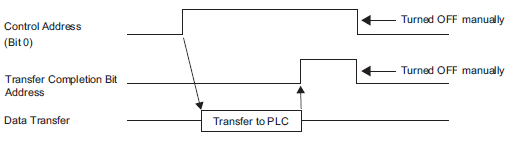
If data cannot be transferred between the PLC and backup memory (SRAM), the internal device for the Special Relay Area LS2032 bit 10 turns ON. To transfer data again, turn OFF the [Control Word Address] bit 0 temporarily. Then, after setting the communication cycle time as either your standard communication cycle time or 150ms (whichever is longer), turn it ON.