(1/4)
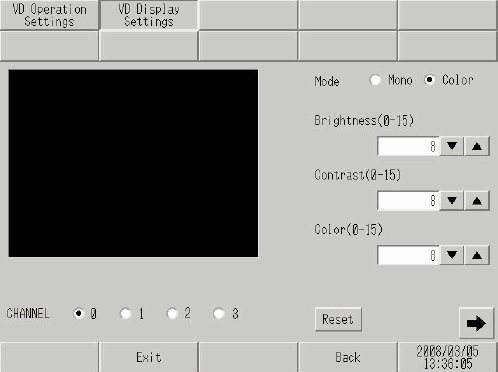
CHANNEL
Select the channel set in the video window from 0 to 3.
Mode
Select the video input mode from [Color] and [Mono].
Brightness
Set the brightness of the screen. The available range is between 0 and 15.
Set the contrast of the screen. The available range is between 0 and 15.
Color
Set the color tone of the screen. The available range is between 0 and 15.
Reset
Reset the settings of the selected channel to the initial values.
(2/4)
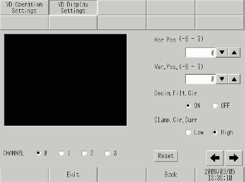
CHANNEL
Select the channel set in the video window from 0 to 3.
Hor.Pos.
Set up the horizontal position (-8 to +7) of the video input signal.
Ver.Pos.
Set up the vertical position (-8 to +7) of the video input signal.
Decim.Filt.Cir
Turn ON/OFF the decimeter circuit included in the decoder. When monochrome signals are used, the image quality may be better when the signal processing filter (decimeter) is not activated. Under normal conditions, leaving this option set to [ON] presents no problem.
Clamp.Cir.Curr
Select the current setting for the clamp circuit from [Low] and [High]. If the video input signal is outside of the specifications, the synchronization signal or the black level cannot be detected, resulting in an unstable screen display. In such a case, changing the internal current for the clamp circuit may improve the screen.
Reset
Reset the settings of the selected channel to the initial values.
(3/4)
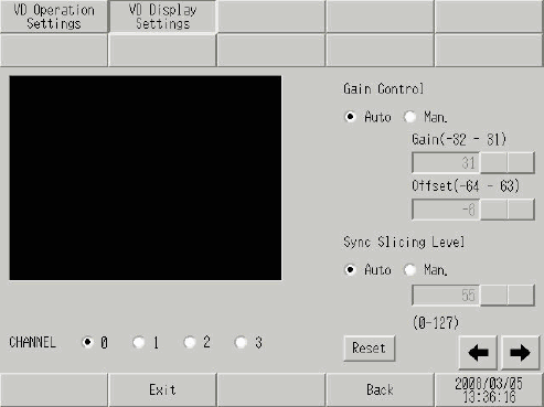
CHANNEL
Select the channel set in the video window from 0 to 3.
Gain Control
Set the gain control of the digital amplifier circuit. This setting is common to all channels.
Gain
When the gain control is set to [Man] (Manual), set [Gain] (amplification factor) from -32 to +31.
Offset
When the gain control is set to [Man] (Manual), set [Offset] (black level) between -64 to +63.
![]()
Offset is not displayed when [VM Unit (3000)] is selected in the [Image Unit] settings in the [System Settings].
Sync Slicing Level
[Auto] or [Man] (Manual) are the available options.
Input field
[Sync Slicing Level]. When this is set to [Man] (Manual), set up between 0 to 127.
Reset
Reset the settings of the selected channel to the initial values.
(4/4)
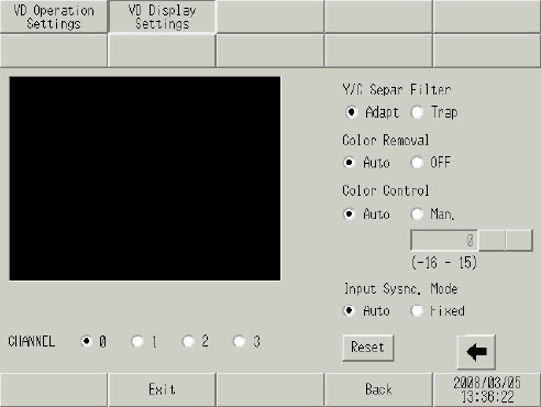
CHANNEL
Select the input channel to which the video device is connected from 0 to 3.
Y/C Separ.Filter
Select the input Y/C separation filter. When a vivid image is displayed and noise from color signals is conspicuous, selecting [Trap] may decrease the noise. This setting is common to all channels.
Color Removal
Select whether to turn ON/OFF the color removal function automatically or to turn it OFF forcefully. When the amplitude level of color burst signals is small, the screen may be switched automatically to show monochrome images. [OFF] setting displays images in color. This setting is common to all channels.
Color Control
Change the amplification factor of chroma signals. If the amplitude value of chroma signals (including color burst signals) is outside of the specifications and the adjustment functions have no effect on the ability to obtain optimal images, setting this item manually may be effective. This setting is common to all channels.
Input Sysnc.Mode
Set the depth level to detect synchronization signals. If the depth of the synchronization signals of the video input is not as deep as the specifications or if the signals fluctuate, the synchronization signals are not detected, resulting in a screen which does not lock vertically or horizontally. When this occurs, adjusting the detection level may stabilize the screen. Under normal conditions, leaving this option set to [Auto] presents no problem. This setting is common to all channels.
![]()
Offset is not displayed when [VM Unit (3000)] is selected in the [Image Unit] settings in the [System Settings].
Reset
Reset the settings of the selected channel to the initial values.