-
Select one of the display units that can use EtherNet/IP for external I/O control.

-
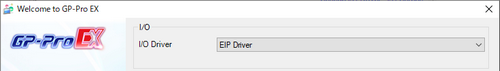
From I/O Driver, select [EIP Drive].
-
From the [Project] menu, point to [System Settings] and click [I/O Driver].
-
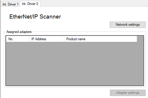
Click the [Int. Driver 2] tab.
-
Set up the network settings. Click [Network settings] to display the following screen.
-
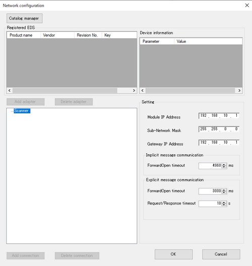
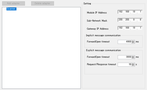
From the tree view, select [Scanner], and from the [Setting], set [Module IP Address], [Sub-Network Mask], and so on, for the Scanner (display unit). Set the [Module IP Address], [Sub-Network Mask] and [Gateway IP Address] to match the display unit settings.
-
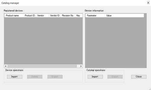
Click [Catalog manager] to display the following screen. The registered devices display in the [Catalog manager].
-
From [Device operations], click [Import] to import the EDS file of the device you are registering. The imported device will appear in [Registered devices].
-
Click [Close] to return to the [Network settings].
-
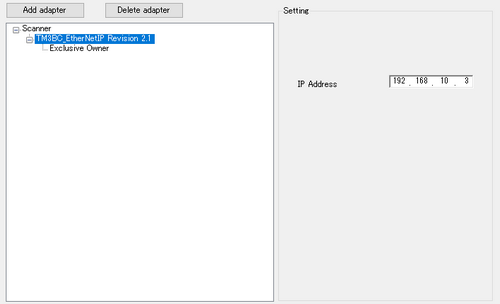
From the [Registered EDS], select the device and click [Add adapter]. The adapter is added to under Scanner in the tree view.
-
Select the added adapter and from the [Setting], set the adapter’s IP address.
-
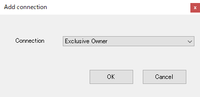
Set the connection to be used by the adapter. Initially, the first connection specified in the EDS file is displayed. To change the connection, click [Delete connection] to remove the displayed connection, click [Add connection] and from the displayed dialog box select the connection you want to use.
-
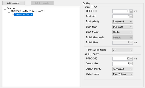
Select the added connection and in the [Setting] area set the connection's [Input T->O] and [Output O->T].
-
Click [OK] to return to the [I/O Driver] setting screen.
-
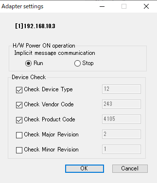
From [Assigned adapters], select the adapter and click [Adapter settings] to display the following dialog box. Configure this as needed.
-
From the [I/O Driver] screen, click [I/O Screen], or from the Work Space select [I/O Screen] in the [Screen List] window to allocate a variable to the displayed bytes. For information on how to assign variables, refer to the following.
 31.10.2 Mapping I/O– EtherNet/IP

-
Create a Logic Screen and a Base Screen to access the allocated variables and transfer them to the display unit.