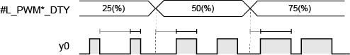
ON duty value is the ON time and OFF time percentage in 1 pulse and sets the ON time in percentage (%).
#L_PWM*_DTY: ON Duty Value
y0: PWM Output
As the output frequency becomes larger, the output waveform set by the ON duty value becomes harder to realize. Therefore, when the output frequency is large, set the setting effective range to correct the output waveform.
How to calculate the effective range
Use the following formulas to calculate the high and low limits of the ON duty effective range.
Upper Limit: 100 - Hardware delay time*1 (microseconds) x Output frequency
Lower Limit: Hardware delay time (microseconds) x output frequency
*1 The hardware delay time shows the total time from ON to OFF (Time to get down to 2.4 V, which is 10% of 24 V), and OFF to ON (Time to get up to 21.6V, which is 90% of 24V). The hardware delay time of this I/O board is 3 microseconds.
For example, when the hardware delay time is 3 microseconds and the output frequency is 10000Hz
Upper Limit: 100-3 x 10-4 x 10000 = 97 (%)
Lower Limit: 3 x 10-4 x 10000 = 3 (%)
The ON duty effective range, therefore, is 3 to 97%.
![]()
Although you can set ON duty to 100% when approximately 3 kHz or less, there is a gap of 1.6 microseconds in each period when it's OFF, despite ON duty being 100%.
For example, for 500Hz, one period is 2 milliseconds during which 1.6 microseconds it's OFF.
ON Duty Value setup method
There are two ways to setup the ON duty value. One is setting up in GP-Pro EX, and the other is setting up with a system variable.
Settings in GP-Pro EX
LT3000 Series / STC6000 Series
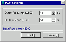
From the [Project] menu, point to [System Settings] and click [I/O Driver]. On the [Int.Driver 1] tab, click [PWM Settings]
In the [PWM Settings] dialog box, specify [ON Duty Value].
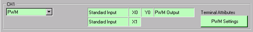
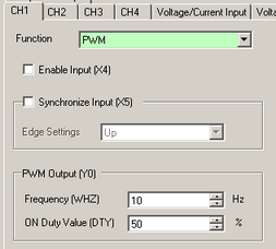
LT4000 Series
From the [Project] menu, point to [System Settings] and click [I/O Driver]. Specify the CH set up in [PWM]. Set an ON duty value to [ON Duty Value].
Set up with System Variables
Define the ON duty value in the system variable (#L_PWM*_DTY). The system variable name adjusts to match the CH pulse output to which it's mapped.