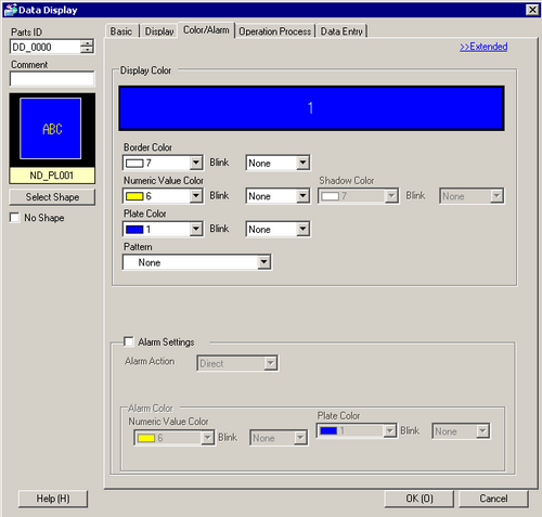
Settings for parts colors and numeric data alarms.
Border Color
Set the border color of the part.
![]()
Depending on the shape, you may not be able to set the color.
Numeric Value Color
Set the color of the numeric value.
![]()
This property cannot be set when [Bitmap Font] is selected.
Shadow Color
Set the color of the Numeric Value's shadow.
![]()
This property cannot be set when [Bitmap Font] is selected.
This property can be set only when [Shadow] is selected for the [Text Attribute] in the [Display] tab.
Depending on the shape, you may not be able to set the color.
Plate Color
Set the background color of the part.
![]()
When setting the plate color to transparent, the display speed may worsen with an increased number of display part positions because the display parts are positioned on the front layer which is used by the animation function.
For information on the front layer, refer to the following.
![]() 21.8 About Object Position and the Layer Separator When Setting Up Animation
21.8 About Object Position and the Layer Separator When Setting Up Animation
When the Plate Color is set to transparent and [No Shape] is selected, only the Numeric Value is displayed. However, the touch range when Allow Input is enabled includes only the Numeric Display, which is smaller than the normal touch range.
When you use a Window screen on the ST3000 Series and GP-3200 Series, do not select transparent as the [Plate Color].
On ST3000 and GP-3200 Series models, the plate color cannot be transparent.
When the plate color is set to transparent, a warning appears when you save the project.
To select [Bitmap Font] and make the font background color the plate color, set the background of the bitmap font transparent. For information on bitmap font transparent settings, refer to the following. (If you disable the transparent setting or select a model that does not support the transparent setting, it displays the model's background color and not the plate color.)
![]() 14.11.1.5 Numeric Display - Display/Basic
14.11.1.5 Numeric Display - Display/Basic
Pattern
Set the background pattern of the part.
Pattern Color
Set the background pattern color.
Blink
Select the blink and blink speed. You can choose different blink settings for the [Border Color], [Numeric Value Color], [Shadow Color], [Plate Color], and [Pattern Color].
![]()
This property cannot be set when [Bitmap Font] is selected.
Depending on your display unit's model and [Color] settings, you may not be able to set Blink (from the [Project] menu, point to [System Settings] and click [Display Unit]).
![]() 1.6 Supported Colors
1.6 Supported Colors
Indirect Area Specification
This property is available when, in the [Basic] tab, you set the [Address Type] to either [Address] or [Device Type & Address], and in the [Color/Alarm] tab you set [Alarm Action] to [Address]. Select the method for specifying the Word Address that stores the alarm's upper and lower limits.
Area After Display Address
The Lower Limit and Upper Limit values are defined in consecutive addresses from the [Monitor Word Address], as specified in the [Basic] tab.
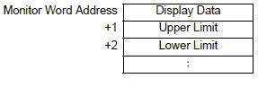
For example, if [Monitor Word Address] is "D100",
Lower Limit is "D101", Upper Limit is "D102".
Individual Settings
Individually define a word address for the [Lower Limit] and a word address for the [Upper Limit].
Alarm Settings
The color can be set to change when the value goes outside of a specified range. Select whether to designate [Alarm].
![]()
The alarm setting can only be set when the number of ranges is one.
If [Allow Input] has been selected in the [Basic] tab, values outside of the alarm range cannot be input by touch.
Alarm Action
Choose the Alarm Action.
Direct
Write a set constant as the alarm's upper and lower limit values. Select the upper and lower limits of the [Display Range] to fit within the ranges of the Max. and Min. values. If the values exceed the range, it will not work properly.
Address
Specify the address where the Upper/Lower Limit values are stored.
Change Color
When the [Alarm Bit Address] turns ON, the color changes and an alarm displays.
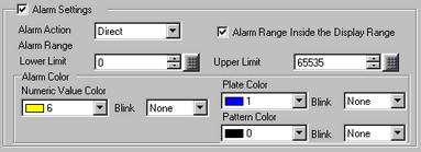
Specify the Alarm Range within the Display range
If [Alarm Action] is [Direct], specify whether the source range of the lower limit and the upper limit is within the [Display Range] in the [Basic] tab. Once selected, you can specify only within the Display Range. Also, enter the lower and upper limit values.
![]()
When the Display Range does not display or the [Display Specification] is [Address], you can set up values within the minimum and maximum range for the defined data type.
Alarm Bit Address
When the [Alarm Action] is [Change Color], input the bit address which acts as a trigger for the color change. When this bit turns ON, the color change will occur.
Alarm Range Upper Limit/Lower Limit
If [Alarm Action] is [Direct], you can set an upper/lower limit value for the alarm range. When [Alarm Action] is [Address] and set to [Individual Settings], you can set the word address where the upper and lower limit values are stored.
Each [Data Type] and [Sign +/-] has a different setup range.
|
Data Length |
Data Type |
Sign +/- |
Range |
|---|---|---|---|
|
8 bit |
Dec |
Disable |
0 to 255 |
|
Enable |
-128 to 127 |
||
|
Hex |
- |
0 to FF (h) |
|
|
Oct |
- |
0 to 377(o) |
|
|
Bin |
- |
00000000 to 11111111 |
|
|
BCD |
- |
0 to 99 |
|
|
16 bit |
Dec |
Disable |
0 to 65535 |
|
Enable |
-32768 to 32767 |
||
|
Hex |
- |
0 to FFFF(h) |
|
|
Oct |
- |
0 to 177777(o) |
|
|
Bin |
- |
0000..0000(16 bits) to 1111..1111(16 bits) |
|
|
BCD |
- |
0 to 9999 |
|
|
32 bit |
Dec |
Disable |
0 to 4294967295 |
|
Enable |
-2147483648 to 2147483647 |
||
|
Hex |
- |
0 to FFFFFFFF(h) |
|
|
Bin |
- |
0000..0000(32 bits) to 1111..1111(32 bits) |
|
|
BCD |
- |
0 to 99999999 |
|
|
Float |
- |
-9.9e16 to 9.9e16 |
Alarm Color
Sets the alarm color.
Numeric Value Color
Select the numeric value color for when the Alarm is displayed.
![]()
This property cannot be set when [Bitmap Font] is selected.
Plate Color
Select the part background color for when the Alarm is displayed.
Pattern Color
Select the background pattern color for when the Alarm is displayed.
Blink
Select the blink and blink speed. You can choose different blink settings in [Numeric Value Color], [Plate Color] and [Pattern Color].
![]()
This property cannot be set when [Bitmap Font] is selected.
Depending on your display unit's model and [Color] settings, you may not be able to set Blink (from the [Project] menu, point to [System Settings] and click [Display Unit]).
![]() 1.6 Supported Colors
1.6 Supported Colors