![]()
-
Please refer to the Settings Guide for details.
 7.9 Settings Guide
Change the type of device by specifying an address conversion pattern. Designate the previous address range and the top address of the destination device/PLC.
![]()
Please refer to the Settings Guide for details.
![]() 7.9 Settings Guide
7.9 Settings Guide
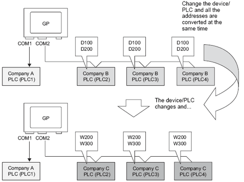
For example:
|
COM1: Company A's PLC, PLC1 (for example, Omron, CS/CJ Series HOST Link) COM2: Company B's PLCs, PLC2, PLC3, PLC4 (for example, 3 units of Mitsubishi Electric, A Series Computer Link) |
|
COM1: Company A's PLC, PLC1 (for example, Omron, CS/CJ Series HOST Link) COM2: Company C's 3 PLCs (for example, 3 units of Yokogawa Electric, Computer Link SIO) |
From the [Project] menu, select [System Settings], and in the window click [Device/PLC].
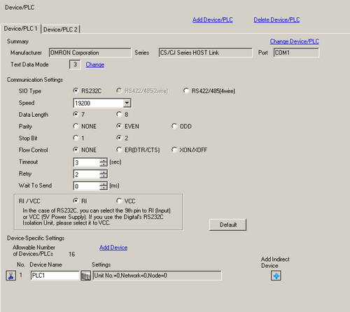
Click the [Device/PLC2] tab, and click [Change Device/PLC].
When the [Change Device/PLC] dialog box appears, set the [Maker] and [Series] of the device/PLC you want to change to.
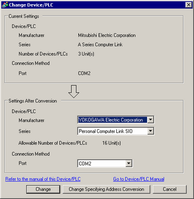
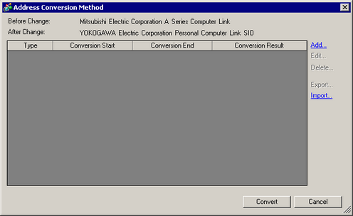
Click [Change Specifying Address Conversion].
When the [Address Conversion Method] dialog box appears, click [Add].
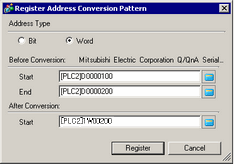
When the [Register Address Conversion Pattern] dialog box appears, set the [Address Type], the [Before Conversion] addresses ([Start] and [End]), and the [After Conversion] address ([Start]).
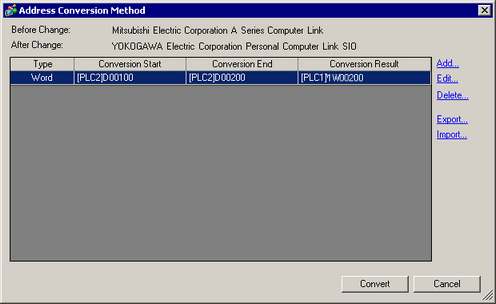
After adding the conversion range to the [Address Conversion Method] dialog box, click [Convert].
![]()
After converting a device/PLC, any parts, D-Scripts, Alarms, etc., must have their device addresses set again. Also, please save any screens that use a Special Switch set to [Screen Change].
If using an Ethernet communication driver when converting multiple device/PLCs, [UDP] and [TCP] cannot be set up in the same driver.
For example, when [Device/PLC1] has been set to MELSEC A Ethernet [UDP] type, [Device/PLC2] cannot be set to MELSEC A Ethernet [TCP] type.