Video common control command (Word Address+0)
The video common control command (address +0) is used to control the operations in the Image Unit window. The following describes the control operations
When the window is displayed, this address area is initialized to the specified value by the Image Unit window.
The following describes the settings when Transparency is enabled.
The color specified for transparency uses the data from the Word Addresses +3 to +5. If the color does not use the data, FFFF(h) is stored in the Word Addresses +3 to +5. Also, in modes transparently displaying colors other than those specified, only Transparent color 1
(Word Address +3) is enabled.
The range for a color specified for transparency is from 0 to 255 and from E1 to E12. When specifying from E1 to E12, set 0x8000 + number. (For example, for E5 set 0x8005.))
The transparent color is acquired from the most significant bit and lower eight bits. Other bits are disabled. Also, when specifying E0 and from E13 to E255, the transparent color is disabled.
While taking a capture, processing of parts and video display are stopped.
If the same file exists on the CF Card, the existing file will be overwritten.
It takes approximately three to five seconds to take a capture (when the image quality is 80).
Video common control command (Word Address+1)
The video common control status (address + 1) writes the results of the operation in the Image Unit window.
The capture status is ON when taking a capture of a JPEG file.
When an error occurs during a capture or JPEG image display, the error code is stored. This error code is stored until the next capture.
For details on JPEG error codes, refer to 27.9.5.2 Snapshot.
Image window display control (Word Address+6)
Defines the image to display in the Image Unit window.
You can select either video image or JPEG image. If you select a video picture, it is displayed on the specified channel by the Image Unit window. For JPEG images, specify the JPEG file number for each channel. You can select to zoom out from the JPEG image.
In addition to the CF card, JPEG images can also be displayed using the files in a USB storage device. In the System Settings, select [Display Unit] and click the [Mode] tab. In the [Screen Capture], select the [Capture Action] check box. When you select the files to be saved in a USB storage device, the files in the USB storage device will be displayed. When you select a CF card, the folder will be the CF card even when you select an FTP server.
The Video Module can display a JPEG image up to 1024 x 768. If the JPEG image is larger than this, then the image is reduced to 1024 x 768 or to the display size specified of either 1/4, 1/6, or 1/64.
Also, for an SVGA model, a VGA model, and an XGA model, sizes of up to 800 X 600, 640 X 480, and 1024 X 768 pixels, respectively, can be displayed on the Image Unit Window. If the image size exceeds the screen size, only part of the image that fits on the screen can be displayed.
When JPEG is set as the initial display, it is not possible to switch between video image and JPEG image using the window display image control flag.
When a JPEG image is being saved, it is not possible to zoom out.
Internal Image Window Screens Control Flag (Word Address+11) / Internal Video Control Channel Number (Word Address+12)
This is the address area for changing the display state of a video picture.
After storing in the internal video channel number in Word Address+12, the control flag is changed to Word Address+11.
Once the coordinate position update bit is ON, the display changes to real time at the coordinate value until the bit turns OFF. When the show window is ON, the area is 0 and cleared.
The video picture display is changed to the settings specified in the bits for UP, DOWN, RIGHT, LEFT, and the plus/minus color value.
When the Color Value Update Bit is ON, it changes the specified values for brightness, contrast and color of the display that are written in the video channel information (Word Address +13 to +36) until the bit turns OFF.
The bit for the plus/minus color value changes the settings for the parameters that are turned ON among the bits for brightness, contrast, and color tone. (These three parameters can be changed simultaneously.)
After prohibiting touch-panel input in the Image Unit window, if the Image unit display is OFF, touch-panel input is enabled.
Video Channel Information (Word Address +13 to +36)/RGB Display Information (Word Address +37 to +42)
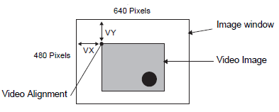
Set the display origin, brightness, contrast and color of each video channel 0 - 3 and RGB display.
Specify which part of the screen to display with the origin point's VX,VY coordinates. Base these coordinates on the video mode and window size.
When Video Input = NTSC, Display Size = Normal
Specify the Width of Video Image + Display Origin (VX) and Height of Video Image + Display Origin (VY) so as to not exceed the window size.
(Width of Video Image + VX ≦ 640, Width of Video Image + VY ≦ 480)
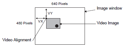
When Video Input = NTSC and Display Size = 1/4
Specify the Double Width of Video Image + Display Origin (VX) and Double Height of Video Image + Display Origin (VY) so as to not exceed the window size.
(Width of Video Image x 2 + VX ≦ 640, Width of Video Image x 2 + VY ≦ 480)
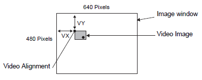
When Video Input = NTSC and Display Size = 1/16
Specify 4XWidth of Video Image + Display Origin (VX) and 4XHeight of Video Image + Display Origin (VY) so as to not exceed the window size.
(Width of Video Image x 4 + VX ≦ 640, Width of Video Image x 4 + VY ≦ 480)
(For example, Video Input = NTSC)
Example use of the Video Control Area
This section gives an example of an operation using the video control area.
Displaying the JPEG file on the CF Card
Display the video capture image "CP00005" saved on the CF Card on Channel 2.
Write the JPEG file number "5" in [Video Control Start Address]+9 (Image Window2).
Write the display size "2" (JPEG 1/4 extension) in bits 8 to 11 of [Video Control Start Address]+6 (Image Window Display Control).
Changing the display size of the Image Window Screen
Change the display size of Channel 2 from Standard to 1/4.
Write "1" (Display Size:1/4 mode) to bits 0 to 1 in the [Video Control Start Address]+25 (Video Window Control Command).
Creating a still image
Create a still image from an image on Channel 2.
Turn ON bit 2 of [Video Control Start Address]+25 (Video Window Control Command of Channel2).
Changing the Video Display position settings
Change the Channel 2 display origin from (0, 0) to (100,100).
Turn ON bit 0 (Coordinate Position Update) of [Video Control Start Address]+11 (Internal Image Window Screens Control Flag).
Write "100" in 2.[Video Control Start Address]+26 (Video Display position settings VX of Channel 2) and +27 (Video Display position settings VY of Channel 2).
Changing the Transparent Color
Turn ON bit +0 (Transparency) of [Video Control Start Address]+0 (Video Common Control Command).
Turn ON bit 1 (Specified Color in Transparency) [Video Control Start Address]+0.
Write the color code in [Video Control Start Address]+3 - 5.