
The display unit clock is used to generate timestamps on file outputs to external memory.
When using GP-4100 series, you can load data from the device/PLC clock into the display unit.
When resetting or turning OFF the display unit, its clock data is initialized.
Use the following screens to set up the clock on the display unit.
The display unit clock is used to generate timestamps on file outputs to external memory.
Supported drivers
You can automatically get clock data if you use one of the following drivers.
To update the clock using a device/PLC driver that is not listed, select the [Customize] check box.
For supported CPUs, see the "GP-Pro EX Device/PLC Connection Manual".
|
Manufacturer |
Series |
|
Mitsubishi Electric Corporation |
FX Series CPU Direct FX Series Computer Link |
|
Omron Corporation |
CS/CJ Series HOST Link |
|
Panasonic Electric Works Co., Ltd. |
FP Series Computer Link SIO |
When the specified device/PLC's communication scan is OFF, you cannot read the clock. You can use LS9550 to check the communication scan status.
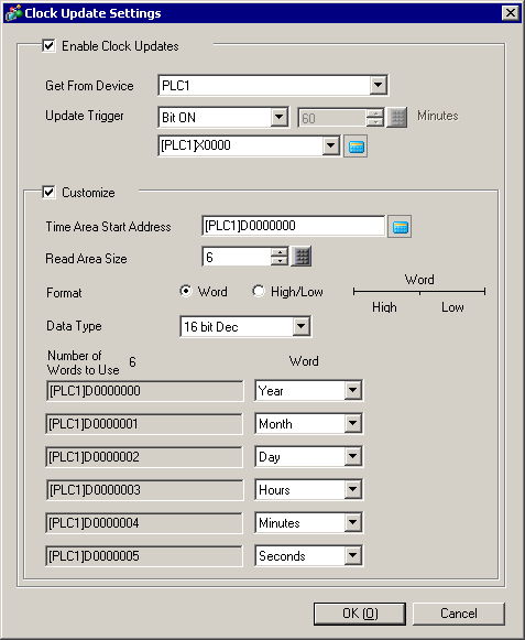
Enable Clock Updates
Display unit loads clock data from the device/PLC using the defined conditions.
Get From Device
Select the device/PLC used for clock information.
Update Trigger
Select the timing for updating the clock from [Frequency], [Bit ON], or [Bit OFF].
Frequency
Specifies the frequency from 1 to 1440 minutes. Updates the clock at the specified frequency.
Bit ON / Bit OFF
Updates the clock when the bit address turns ON or OFF.
When using [Frequency], there is a maximum error of 1 second when updating the clock from the LS area.
When using [Frequency], the clock is updated on the following conditions, in addition to the defined frequency.
Until the clock update is complete, parts on the display unit will not operate.
Powering up the display unit
Going from offline to online mode
After transferring and returning online
(when the display unit is not reset, such as automatic transfer)
Customize
You can use this setting to get clock data stored in the specified address and data format.
Time Area Start Address
Specify the start address where clock data will be stored.
Read Area Size
Specify the number of words for storing clock data from 1 to 6.
Format
Define whether clock data is stored in single word units, or words are separated into High/Low units.
Word
In single word units, stores the year, month, day, hours, minutes, and seconds.
High/Low
In words divided into High/Low units, stores the year, month, day, hours, minutes, and seconds.
Data Type
Choose the data format of the stored clock data from [16 bit Dec], [16 Bit BCD], [32 bit Dec] or [32 Bit BCD].
When using [16 bit Dec] or [16 bit BCD] and the address specified in the [Time Area Start Address] field is 32 bits, no data is stored in the top 16 bits.
When using [32 bit Dec] or [16 bit BCD] and the address specified in the [Time Area Start Address] field is 16 bits, 2 words are used for each clock data.
Number of Words to Use
Displays the number of words used for clock updates, as defined in the [Read Area Size].
Word
Displays the addresses as defined in the [Time Area Start Address] and [Read Area Size] fields.
For each address, specify what is stored in the word, [Year], [Month], [Day], [Hours], [Minutes], or [Seconds]. Select [None] to store no data in the address.
When there is an error in getting data for the seconds, and data for the year, month, day, hours, and minutes is okay, the seconds is reset to zero. An error message displays if there is an error in getting the year, month, day, hours, or minutes.
When there is an invalid value for the year, month, day, hours, or minutes, the value is not stored and an error message dislays. After the error message displays, if the next clock update produces a valid value the error message will clear.
Valid values are as follows.
Year: 0 to 99
Month: 1 to 12
Day: 1 to 31 (Top limit depends on the number of days in the month)
Hours: 0 to 23
Minutes: 0 to 59
Seconds: 0 to 59
Although the day of the week (stored in LS2054) is not updated using this feature, the value in the day of the week storage area (LS9310) is calculated when the date is updated. A.1.4.4 LS9000 Area