![]()
For details about the setting screen, refer to the setting guide.
 M.18.3.2 Peripheral Settings
- I/O Monitor - Model (Input)
M.18.3.2 Peripheral Settings
- I/O Monitor - Model (Input)
Check if the input and output operate normally.
Can the device connected to the FLEX NETWORK board perform input and
output functions normally?
Check if GP-Pro EX settings are the problem, or the display unit is the
problem.
![]()
For details about the setting
screen, refer to the setting guide.
![]() M.18.3.2 Peripheral Settings
- I/O Monitor - Model (Input)
M.18.3.2 Peripheral Settings
- I/O Monitor - Model (Input)
When DIO (Example: FN-X16TS) is used
Go to offline mode and touch [Peripheral Settings] on the item changeover switch.
[Peripheral Settings] screen opens. Touch [I/O Driver] and then [FLEX NETWORK Driver].
[I/O Driver] screen opens. Touch [I/O Monitor].
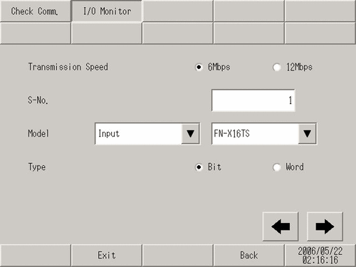
[I/O
Monitor] screen opens. Set the [Transmission
Speed], [S-No.], [Model], and [Type].
(Example, S-No.= 1, Model= Input FN-X16TS, Transmission
Speed= 6Mbps, Type=Bit)
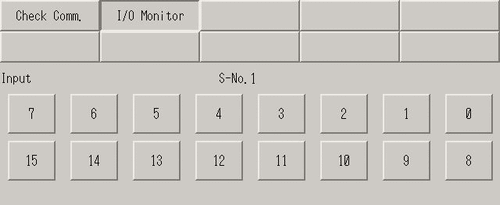
The bit monitor screen is displayed,
showing the ON/OFF status. A protruded switch indicates OFF and a depressed
switch indicates ON. If the connected device is operating normally, check
the settings in GP-Pro EX. If the connected device does not operate normally,
check the wiring between the display unit and the connected device, and
then check the following items.
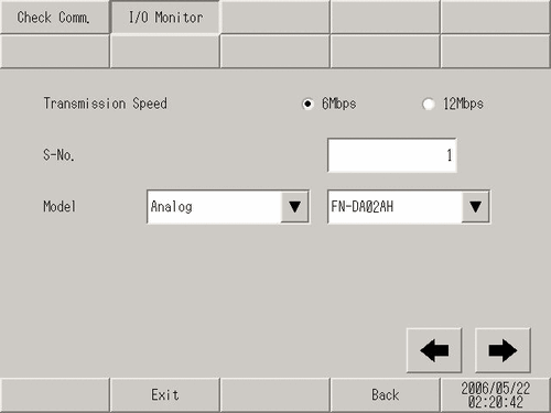
When an analog unit (Example: FN-AD02AH) is used
Go to offline mode and touch [Peripheral Settings] on the item changeover switch.
[Peripheral Settings] screen opens. Touch [I/O Driver] and then [FLEX NETWORK Driver].
[I/O Driver] screen opens. Touch [I/O Monitor].
[I/O
Monitor] screen opens. Set the [Transmission
Speed], [S-No.], [Model], and [Type].
(Example, S-No.= 1, Model= Input FN-AD02AH, Transmission
Speed= 6Mbps
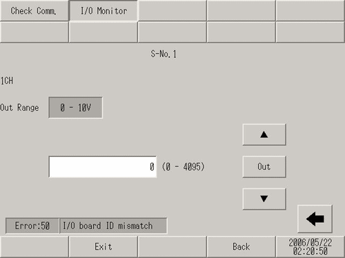
Touch this switch to go to the next
screen and set [CH] (channel)
and [Range].
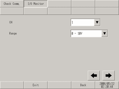
The input monitor screen is displayed.
The input status is indicated with an integer value. If the connected
device is operating normally, check the settings in GP-Pro EX. If the
connected device does not operate normally, check the wiring between the
display unit and the connected device, and then check the following items.
Checking communication to ensure proper cable connection
Check whether the FLEX NETWORK unit connected to the FLEX NETWORK board can communicate properly.
![]()
For details about the setting
screen, refer to the setting guide.
![]() M.18.3.1 Peripheral Settings - Check Communication
M.18.3.1 Peripheral Settings - Check Communication
Go to offline mode and touch [Peripheral Settings] on the item changeover switch.
[Peripheral Settings] screen opens. Touch [I/O Driver] and then [FLEX NETWORK Driver].
[I/O Driver] screen opens. Touch [Check Comm.].
[Start]:
Touch the button.
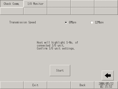
The screen for communication check execution
is displayed. When no problem is found with the communication, the total
number of units that communicated successfully and the number of S-No.
assigned to the units are highlighted. If the communication is successful,
please check whether the device connected to the FLEX NETWORK unit operate
properly or the cable is correct. If communication fails, check the communication
cable for breaks, the power supply of the unit, and the termination resistor
of the unit. If the problem continues, the unit or main unit may be faulty.
Please contact your local distributor.
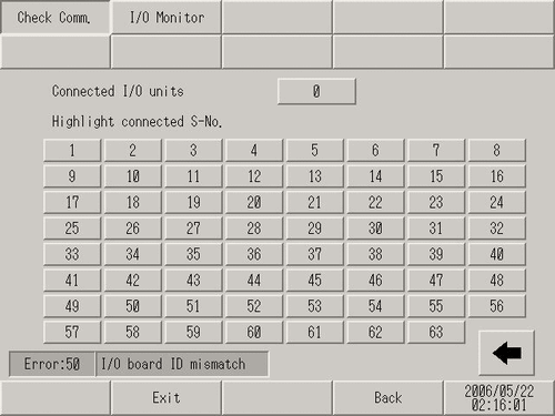
The following list shows the I/O units supported by the communication check. For example, when setting FN-X16TS(1),1 S-No.1 and FN-XY32SKS (4),1,S-No.2, S-no.1 to 5 are highlighted on the screen above.
|
Type |
Model |
No. of stations to be occupied |
|---|---|---|
|
DIO |
FN-X16TS |
1 |
|
FN-X32TS |
2 | |
|
FN-Y08RL |
1 | |
|
FN-Y16SK |
1 | |
|
FN-Y16SC |
1 | |
|
FN-XY08TS |
1 | |
|
FN-XY16SK |
1 | |
|
FN-XY16SC |
1 | |
|
FN-XY32SKS |
4 | |
|
Analog |
FN-AD02AH |
1 |
|
FN-AD04AH |
4 | |
|
FN-DA02AH |
1 | |
|
FN-DA04AH |
4 | |
|
High Speed Counter Unit |
FN-HC10SK |
8 |
|
Single-Axis Positioning Unit |
FN-PC10SK |
4 |