![]()
I/O check is enabled only with the EX module that has been specified in GP-Pro EX.
For details about the setting screen, refer to the setting guide.
 M.23.3.2 Peripheral Settings - I/O Driver (EXM Driver), I/O Monitor (DIO settings)
Check if the EX modules are connected normally to the LT series and check if the input and output of the device connected to the EX modules are operating normally, to judge whether the problem is caused by the settings of the GP-Pro EX or of the LT series.
When the DIO module is used:
![]()
I/O check is enabled only with the EX module that has been specified in GP-Pro EX.
For details about the setting screen, refer to the setting guide.![]() M.23.3.2 Peripheral Settings - I/O Driver (EXM Driver), I/O Monitor (DIO settings)
M.23.3.2 Peripheral Settings - I/O Driver (EXM Driver), I/O Monitor (DIO settings)
Go to offline mode and touch [Peripheral Settings] on the item changeover switch.
[Peripheral Settings] screen opens. Touch [I/O Driver] and then [EXM Driver].
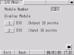
[EXM Driver] window opens. Touch [I/O Monitor] to display the number of currently connected modules and the module numbers. If the connected module is not displayed, check the wiring between the module and the connected device.
![]()
When the LT3200 series is used, up to 2 modules are displayed. When the LT3300 series is used, up to 3 modules are displayed.
Touch each module number. After the corresponding screen appears, select the type of input/output data, [Bit] or [Word]. (Example, DIO=Output 16 points, Type=Bit)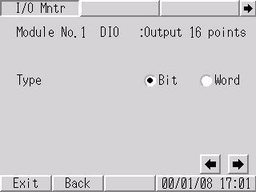
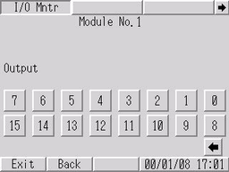
If you shift between screens with the ![]() switch, the input/output execution screen appears, which displays the input ON/OFF status and allows you to execute the output. If the connected device is operating normally, check the settings in GP-Pro EX. If the connected device is not operating normally, check the wiring between the EX module and the connected device.
switch, the input/output execution screen appears, which displays the input ON/OFF status and allows you to execute the output. If the connected device is operating normally, check the settings in GP-Pro EX. If the connected device is not operating normally, check the wiring between the EX module and the connected device.
When the analog module is used:
![]()
I/O check is enabled only with the EX module that has been specified in GP-Pro EX.
For details about the setting screen, refer to the setting guide.![]() M.23.3.2 Peripheral Settings - I/O Driver (EXM Driver), I/O Monitor (Analog settings)
M.23.3.2 Peripheral Settings - I/O Driver (EXM Driver), I/O Monitor (Analog settings)
Go to offline mode and touch [Peripheral Settings] on the item changeover switch.
[Peripheral Settings] screen opens. Touch [I/O Driver] and then [EXM Driver].
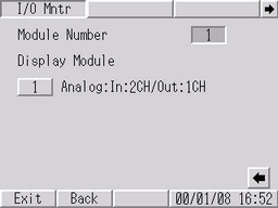
[EXM Driver] window opens. Touch [I/O Monitor] to display the number of currently connected modules and the module numbers. If the connected module is not displayed, check the wiring between the module and the connected device.
![]()
When the LT3200 series is used, up to 2 modules are displayed. When the LT3300 series is used, up to 3 modules are displayed.
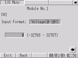
Touch each module No. After the corresponding screen appears, specify the I/O channel number, data format, and data range. (Example, CH=1, Data Format=Voltage (0-10 V), Data Range=Fixed)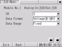
If you shift between screens with the ![]() switch, the input/output execution screen appears, which displays the input value and allows you to execute the output. If the connected device is operating normally, check the settings in GP-Pro EX. If the connected device is not operating normally, check the wiring between the EX module and the connected device.
switch, the input/output execution screen appears, which displays the input value and allows you to execute the output. If the connected device is operating normally, check the settings in GP-Pro EX. If the connected device is not operating normally, check the wiring between the EX module and the connected device.