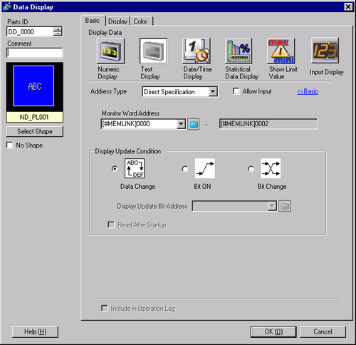
You can indirectly specify an address for the Text Display, or set up an update condition for displayed text.
Address Type
You can define the display address (Monitor Word Address) in the following ways: [Direct Specification], [Address], or [Device Type Address].
Allow Input
You can accept input from a keypad, bar code reader, or a two-dimensional bar code reader. Select this check box to display the [Data Entry] tab.
Monitor Word Address
You can have a real-time numeric display of data stored in the Word Address specified here. To indirectly specify the Monitor Word Address, in the [Address Type] list select [Address] or [Device Type Address].
Address
Indirectly designates to the device specified in [Base Address].
Base Address/Offset Value Specification Address
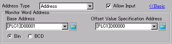
The [Base Address] becomes the standard indirectly designated address.
In [Offset Value Specification Address], set the address that stores the offset value from the [Base Address].
For example, when you indirectly specify [Monitor Word Address] D35
[Base Address] = D10 [Offset Value Specification Address] = D100
The data in [Offset Value Specification Address] is handled as the offset value from the [Base Address].
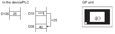
The [Base Address] (D10) is added to the [Offset Value Specification Address] (D100)'s data, which is "25", and the resulting address D35's data "40" displays.
![]()
If the [Base Address] + [Offset Value] operation results in overflowing digits (more than 16 bit), the correct Monitor Word Address cannot be requested. In this case the Monitor Word Address will be undefined.
Bin, BCD
Choose the type of data stored in the [Offset Value Specification Address] from [Bin] or [BCD].
Device Type Address
Indirectly designates both the device and address.
Device/PLC
When [Address Type] is [Device Type Address], select which device/PLC's address to indirectly designate.
Device Specification Start Address
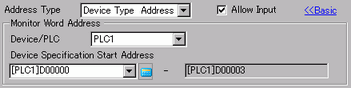
Input the start address of the word address to specify the Display Address in [Device Specification Start Address]. Store the Address Mode in [Device Specification Start Address]. Address Mode is the mode to determine if the Device Address is for Internal or External (PLC) Device. Store the Device Code and the Address Code in the three Words following [Device Specification Start Address]. The word address specified with the Device Code and the Address Code will be displayed.
For example, when you indirectly specify [Monitor Word Address] CN35
[Device Specification Start Address] = D100
[Address Mode] = External (PLC) Device
[Device Code] = CN:0061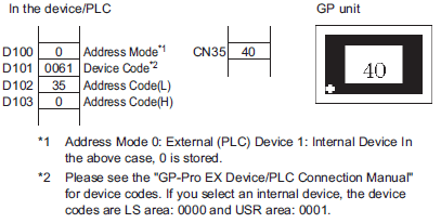
The address designaged by D100, D101, D102, and D103 is CN35. Its data, "40" displays.
![]()
If the indirectly-designated address is out of range or does not exist, a communication error will occur. An error can affect the screen update. When an error occurs, check the indirectly-designated data and write the correct value to the device/PLC address to restore the screen update.
Display Update Condition
Designate the condition which will update the display. This can only be set on the Detail screen.
Data Change
The display is updated when a change occurs in the data stored in the [Monitor Word Address] on the [Basic] tab.
Bit ON
The display is updated when a bit stored in the [Monitor Word Address] on the [Basic] tab turns ON.
Bit Change
The display is updated when a bit stored in the [Monitor Word Address] on the [Basic] tab changes state from ON to OFF or from OFF to ON.
![]()
When [Data Entry] is enabled, [Bit ON] or [Bit change] cannot be set.
When Visibility Animation is set and [Bit ON] or [Bit Change] is selected, the following operation will occur.
When Bit On or Bit Change is selected in the invisible state, the Display Text will be updated while maintaining the invisible state. Subsequently, when it is in the visible state, the updated Text will be displayed.
Also, when the Monitor Word Address value is changed, it will maintain the invisible state. Similar to regular operation, the Display Text will not be updated even if the Monitor Word Address value is changed. Subsequently, when it enters the invisible state, Text that has not been updated will be displayed.
Display Update Bit Address
Defines the ON/OFF trigger bit address for when [Display Update Condition] is set to [Bit ON] or [Bit Change].
Read After Startup
When the text data has a large volume or many Text Display parts are set on the single screen, select this check box for each Text Display to increase other tags' display speeds. However, when this is checked, Text Display speeds will decrease.
![]()
You can set the Read After Startup when [Display Update Condition] is set to [Bit ON] or [Bit Change].
![]()
After the data has been changed in the monitor address, please change the [Display Update Bit Address] so the text displays. If the changing order is reversed, the text may not display properly.
If the [Display Update Bit Address] changes immediately after the text data changes in the device/PLC, there may be instances where the text does not display correctly. In this case, program the device/PLC to use the [Wait to Send] to slightly delay the trigger bit change.
The [Wait to Send] period depends on the amount of placed parts, scan time, baud rate, and the number of characters used.