Multiple PLC Connection Methods
Multiple PLCs can be connected.
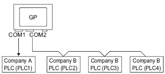
When Using COM1 and COM2
For example, Company A's driver (serial communication) is set to COM1 and Company B's driver is set to COM2 (serial communication).
![]()
A different driver can be designated for each COM port. However, each COM port can only have a single driver.
You can connect multiple devices with the same driver to each COM Port. However, the allowable number of devices/PLCs varies depending on the driver. Refer to the "GP-Pro EX Device/PLC Manual" for the allowable number of devices/PLCs.
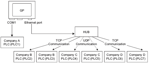
For example, Company A's driver (serial communication) is set to COM1, and Company B, C, and D's drivers are set to the Ethernet port (Ethernet communication).
![]()
A maximum of four drivers can be used by the ports. However, one driver can be configured per COM port, and the remainder be used by the Ethernet port, or all 4 can be used by the Ethernet port and none by the COM ports. In the above example, COM1 has one driver set up (Company A's PLC), so the Ethernet port can handle three additional types of drivers (Company B, C, and D).
When using an Ethernet communication driver with multiple connections, [UDP] or [TCP] cannot be set up in the same driver.
For example, when [Device/PLC1] has been set to MELSEC A Ethernet [UDP] type, [Device/PLC2] cannot be set to MELSEC A Ethernet [TCP] type.
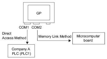
Direct Access Method + Memory Link Method
Devices/PLCs and hosts (PCs, Microcomputer boards, etc.) can be connected at the same time.
When using Direct Access Method and Memory Link Method
For example, Company A's PLC is connected to COM1 by the direct access method, and the micro-computer board is connected to COM2 by the memory link method.
System Data Area/LS Area for Use with Multiple Devices/PLCs
Refer to the A.1.4.5 Device/PLC System Data Area Allocation Procedure or "GP-Pro EX Device/PLC manual" for details on the system data area.
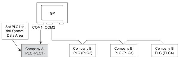
When multiple PLCs are connected to the display unit, the system data area can only have one PLC connected to it.
For example, In the following image, when four PLCs are connected to the display unit, only one of PLC1 to PLC4 can be set to the system data area.
Direct Access Method + Memory Link Method
When communicating by direct access and memory link, each method uses a separate LS area. However, the system data area, the special relay area, and the LS9000 area are shared.
For example, in the following image, a PLC and microcomputer board are both connected to the display unit, the display unit has a direct access method LS area and a memory link method LS area.
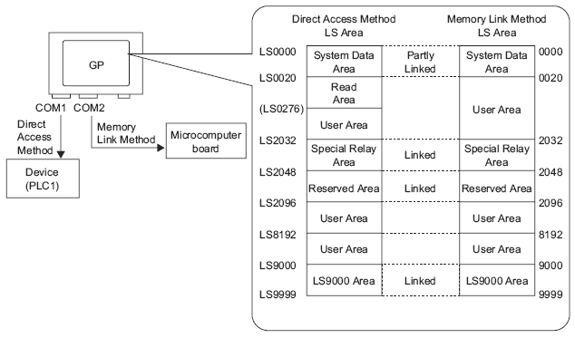
![]()
For address details, see A.1 Communication or the "GP-Pro EX Device/PLC manual".