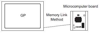
The Memory Link Method is used to connect with devices, or hosts, that do not contain a communication protocol, such as a computer or a microprocessor board.
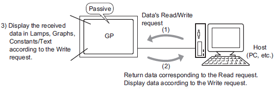
In the Memory Link Method, a data read/write request occurs from the host to the display unit, as in the following image. The display unit displays data that was sent in response to the host's write request. In response to a read request, the display unit sends stored data to the host.
![]()
Communication based on the Memory Link Method is accomplished by executing a program on the host.
For the display unit to get the necessary display data from the host, set an address that can reference data and set the Parts or script features. There are two types of address inside the display unit that can be set as a reference destination.
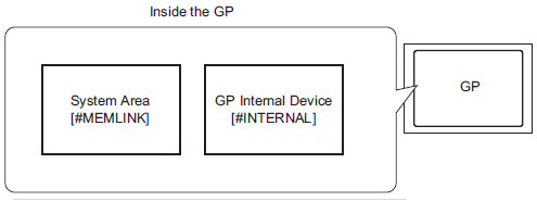
Memory Link System Area Addresses
The System Area is used to request the host's read/write. It is the Memory Link Method's communication area.
For details regarding the System Area, please refer to A.1.5 System Area (Memory Link Area).
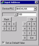
For example, to set a Word Switch address settings, select [#MEMLINK] from [Device/PLC] and enter the address (for example, "0100").
For example, an Input Address screen on a Word Switch.
For example, you can use the internal device as a temporary storage area when you need to refer to calculated values. You cannot use the internal device with Memory Link communication.
For the [Device/PLC] select [#INTERNAL], which refers to the display unit's internal device, and enter that address (for example, "USR00100").
For example, an Input Address screen on a Word Switch.
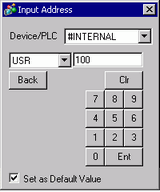
![]()
When using Memory Link communication with the display unit internal device [#INTERNAL], you can only use the [USR] area. When using Direct Access communication or other device/PLC drivers, you can also use the [#INTERNAL] [LS] area.