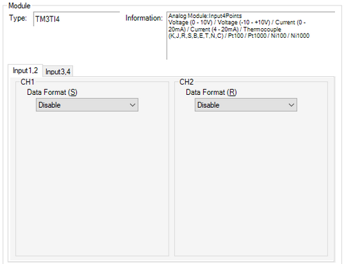
Data Format
Select the format for entering data into the module's analog input terminal.
![]()
When [Disable] is selected in [Data Format], the values in [User Defined (Maximum/Minimum)] will be set to defaults.
If [Data Type] is Voltage
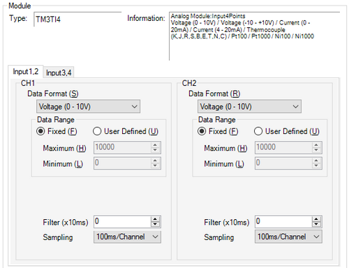
Input
Configure the module's analog input terminal settings.
Data Format
Select the data format from the following.
[Voltage (0 - 10V)]
[Voltage (-10 - +10V)]
Fixed
The analog value in the voltage setting is displayed inside the range of the selected data format. The value on the display unit is the input value multiplied by 1000.
User Defined (Maximum/Minimum)
The analog values in the voltage input settings appear within the range of [Maximum] and [Minimum] settings. The available values are as follows.
Maximum: minimum to 32767
Minimum: -32768 to maximum
Filter (x 10 ms)
In 10 ms increments, set the time to reach 63% of the calculated value in the [Sampling] property. It then takes 5 times the set time to reach 99% of the value.
Note that if 0 is set, no filter is applied and the calculated value in the [Sampling] property is used.
Sampling
Select the sampling period for calculating the moving average of input values, from [1ms/Channel], [10ms/Channel], and [100ms/Channel]. The available sampling periods depend on the TM3 module used.
If [Data Format] is Current

Inputs (CH1 to CH4)
Configure the module's analog input terminal settings.
Data Format
Select the data format from the following.
[Current (0 - 20mA)]
[Current (4 - 20mA)]
Fixed
The analog values in the current setting are displayed inside the range of the selected data format. The value on the display unit is the input value multiplied by 1000.
User Defined (Maximum/Minimum)
The analog values in the current's input settings appear within the range of [Maximum] and [Minimum] settings. The available values are as follows.
Maximum: minimum to 32767
Minimum: -32768 to maximum
Filter (x 10 ms)
In 10 ms increments, set the time to reach 63% of the calculated value in the [Sampling] property. It then takes 5 times the set time to reach 99% of the value.
Note that if 0 is set, no filter is applied and the calculated value in the [Sampling] property is used.
Sampling
Select the sampling period for calculating the moving average of input values, from [1ms/Channel], [10ms/Channel], and [100ms/Channel]. The available sampling periods depend on the TM3 module used.
If [Data Format] is Temperature
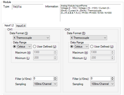
Input
Configure the module's analog input terminal settings.
Data Format
Select the data format from the following.
[K Thermocouple]
[J Thermocouple]
[R Thermocouple]
[S Thermocouple]
[B Thermocouple]
[E Thermocouple]
[T Thermocouple]
[N Thermocouple]
[C Thermocouple]
[Pt100]
[Pt1000]
[Ni100]
[Ni1000]
Celsius/Fahrenheit
The sensor temperature ranges for the [Data Format] are as follows. The value on the display unit is the input value multiplied by 10.
K Thermocouple -200 to 1300℃ / -328 to 2372℉
J Thermocouple -200 to 1000℃ / -328 to 1832℉
R Thermocouple 0 to 1760℃ / 32 to 3200℉
S Thermocouple 0 to 1760℃ / 32 to 3200℉
B Thermocouple 0 to 1820℃ / 32 to 3308℉
E Thermocouple -200 to 800℃ / -328 to 1472℉
T Thermocouple -200 to 400℃ / -328 to 752℉
N Thermocouple -200 to 1300℃ / -328 to 2372℉
C Thermocouple 0 to 2315℃ / 32 to 4199℉
Pt100 -200 to 850 ℃ / -328 to 1562℉
Pt1000 -200 to 600℃ / -328 to 1112℉
Ni100 -60 to 180℃ / -76 to 356℉
Ni1000 -60 to 180℃ / -76 to 356℉
Example: Pt1000
Celsius
The displayed value (-2000 to 6000) is 10 times the input value ranging from -200.0℃ to 600.0℃.
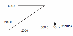
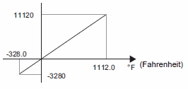
Fahrenheit
The displayed value (-3280 to 11120) is 10 times the input value (-328.0℉ to 1112.0℉).
Filter (x 10 ms)
In 10 ms increments, set the time to reach 63% of the calculated value in the [Sampling] property. It then takes 5 times the set time to reach 99% of the value.
Note that if 0 is set, no filter is applied and the calculated value in the [Sampling] property is used.
Sampling
Select the sampling period for calculating the moving average of input values, from [1ms/Channel], [10ms/Channel], and [100ms/Channel]. The available sampling periods depend on the TM3 module used.