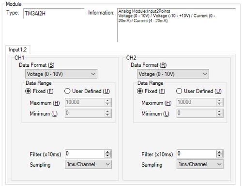
Inputs (CH1 to CH2)
Configure the module's analog input terminal settings.
Data Format
Select the data format from the following.
[Disable]
[Voltage (0 - 10V)]
[Voltage (-10 - +10V)]
[Current (0 - 20mA)]
[Current (4 - 20mA)]
![]()
When [Disable] is selected in [Data Format], the values in [User Defined (Maximum/Minimum)] will be set to defaults.
Fixed
The analog values in the voltage and current input settings are displayed inside the range of the data format. The value on the display unit is the input value multiplied by 1000.
![]()
This is displayed only when [Voltage (0 - 10V)], [Voltage (-10 - +10V)], [Current (0 - 20mA)] or [Current (4 - 20mA)] is selected in [Data Format].
User Defined (Maximum/Minimum)
The analog values in the voltage and current input settings appear within the range of [Maximum] and [Minimum] settings. The available values are as follows.
Maximum: minimum to 32767
Minimum: -32768 to maximum
![]()
This is displayed only when [Voltage (0 - 10V)], [Voltage (-10 - +10V)], [Current (0 - 20mA)] or [Current (4 - 20mA)] is selected in [Data Format].
Filter (x 10 ms)
In 10 ms increments, set the time to reach 63% of the calculated value in the [Sampling] property. It then takes 5 times the set time to reach 99% of the value.
Note that if 0 is set, no filter is applied and the calculated value in the [Sampling] property is used.
Sampling
Select the sampling period for calculating the moving average of input values, from [1ms/Channel], [10ms/Channel], and [100ms/Channel]. The available sampling periods depend on the TM3 module used.