The following describes how to save to the CF card still images of video from channel 1.
-
From the [Project] menu, point to the [System Settings], and click [Image Unit].
-
In the [Image Unit] field, verify that [VM Unit (3000)] is selected.
Under [Video Control Start Address], select [Enable]. 42 Words from the setup address control the video display.

-
Specify the video control start address.

-
The settings for the [Video Control Start Address] range from LS20 to LS1989 and LS2096 to LS8957. If values outside this range are specified, none of the VM functions will operate.
-
From [Video Input], select [NTSC]. (If the video signal is PAL, select [PAL].)
-
In the [Screen] menu, select [New Screen], or click  icon. The [New Screen] dialog box appears.
-
From [Screens of Type] select [Image Unit Window]. Set the [Screen Number] and [Title] then click [New]. (For example, [Screen Number] 1, [Title] Video)
-
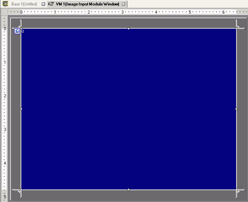
The Image Unit Window appears.
-
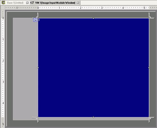
Select the display area (blue area) by clicking it, and adjust the size of the border by dragging it.
As necessary, drag the Resize Boundary  located at the four corners of the screen to adjust the screen size.
-
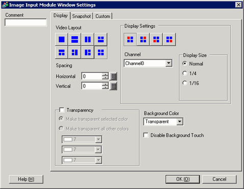
Double-click the blue display area. The following dialog box appears. In [Video Layout] click  .
.
-
In the [Display] area, click  , and under the [Channel], select the camera image to be displayed in this upper left area (for example, Channel 0).
Also select the size of the image (for example, 1/4).
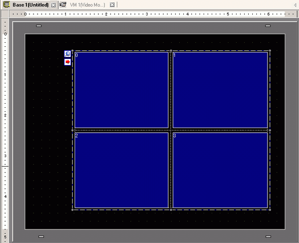
Similarly, select the channels and display sizes for the images displayed in the upper right, lower left, and lower right areas.
-
If the selected [Display Size] is larger than the display unit or the blue display area, the entire image will not display. You can use [Video Display position] on the [Custom Settings] tab to specify which part of the input image to be displayed. If you want to display the entire image, set the [Display Size] smaller than the size of the blue display area.
-
The display size varies depending on a type of display unit and display mode.
 28.13.2 Display Size - RGB Unit/DVI Unit
-
Specify the values for the space between the screens. (For example: 10 x 10)
-
Open the [Snapshot] tab, and select the [Video capture] check box.

-
Select the channel to capture. (For example, [Channel 0])

-
You can capture screens for one channel only. You can capture screens only for video images.
-
Under [JPG File Number], select [Direct], and specify the JPEG file number for the file you are creating.

-
To save to the USB storage or FTP server, from the [Project] menu point to [System Settings] and click [Display Unit], in the [Mode] tab and select the [Capture Action] check box, and specify the destination.
-
Click [OK] to finish and exit the [Image Unit Window] settings.
-
On the [Parts (P)] menu, select [Image Unit Display (V)] or click  to place the [Image Unit Display] on the screen.
-
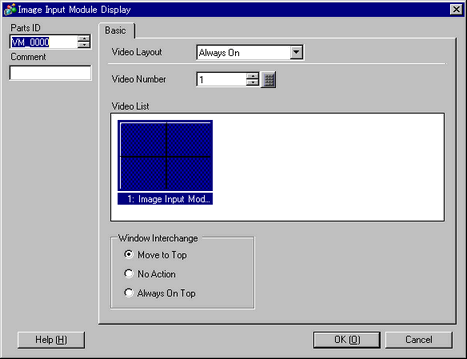
Double-click the [Image Unit Display]. The following dialog box appears.
In the [Video Layout] list, select [Always ON]. In the [Video Number] list, specify the video display number (for example, 1) and click [OK].
-
Click the  icon on the [Image Unit Display] in order to display the corresponding video screen. This feature is useful for checking the video settings because it makes screen changes easy.