3.2 Creating a Project - Start / Create Screen / Save / Exit

This section explains the workflow from starting GP-Pro EX to creating, saving, and exiting projects.

Starting

  1. Double click the shortcut on the desktop, or from the [Start] menu, click [GP-Pro EX *.*] - [GP-Pro EX *.*] (*.* indicates the version number).

  2. When you launch GP-Pro EX, the following dialog box appears.
    From the next time you start GP-Pro EX, you can check for software update information every time you launch GP-Pro EX. Select the [Check for Update when the program starts] check box, then click [OK].
    If you want to check for updates only when necessary, clear the check box and click [OK].

    • For the procedure on checking for updates only when required, see the following.
      3.10 How to Update GP-Pro EX

    • When starting up GP-Pro EX for the first time, the user registration webpage appears.

  3. The [Welcome to GP-Pro EX] dialog box appears. Select [New] and click [OK].

    • To create a new project, from the [Project (F)] menu, select [New (N)]. You can also click the , to create a new project. The [Welcome to GP-Pro EX] dialog box appears.

    • You can create a project file based on sample projects stored in the [Sample] folder. In the welcome dialog box, select [Create Project from Sample]. The project will be read-only. Save the file using the [Project (F)] menu's [Save As (A)] command.

  4. In the next screen, from [Series] select [GP3000 Series], and then select the screen size series, [Model] and [Orientation]. Then click [Next].
    1.4 Supported Model List

    • [Specifications] shows the specifications of the selected display model.

    • If [SP5000 Series] is selected, select [Box Module] and [Display Module].

    • If you select [GP2000 Series], GP-Pro EX exits and GP-PRO/PBIII for Windows starts. GP-PRO/PBIII for Windows does not start if not installed.

    • When you select [IPC Series (PC/AT)], which does not support portrait orientation, there is no [Orientation] property. Specify the data display size in [Screen Size].

  5. The following screen is displayed. Set [Open] the port of the function you want to use, then click [Next].

    • If you selected a model that does not support the port management function, this screen does not display.
      For models that support opening or closing ports, refer to the following.
      1.5 Supported Features

    • Click [Set as Default] to set the above settings as the default values. The next time you create a project, the registered settings are used as the initial values.

  6. The following screen is displayed. Select [Manufacturer], [Series], and [Port], and then click [Communication Settings].

    • To create a screen without configuring communication settings for the device/PLC series, click [New Screen]. The screen editor will display [Base 1].
      To create a logic program, click [New Logic] to display the logic editor [Main].
      30. Logic Programming Logic Programming

    • If you select the [Use System Area] check box, you can set up the display unit's internal system data area on the device/PLC.
      5.4.6 System Settings [Display Unit] - [System Area] Settings Guide

    • When selecting the [LT3000 Series], click [Next] to show the following screen and then select the I/O driver to be used.

  7. The [New Project File] dialog box closes and the [System] tab is displayed in the main window. Click [Device/PLC1].

  8. When [Device/PLC] is displayed, specify the communication settings.

    • The [Communication Settings] details differ depending on the device/PLC series. See the "GP-Pro EX PLC/Device Connection Manual" for your device/PLC.
      It is recommended to keep the default settings for [Timeout], [Retry], and [Wait to Send].

Creating/Saving

  1. Open the Screen List window and double-click the base screen.

    • If the [Screen List] is not on the workspace, from the [View (V)] menu, point to [Work Space (W)] and select [Screen List (G)].

    • To create a logic program, double-click the logic screen currently displayed. If you select a model that does not support the logic features, you can create the logic program but the program will not run on the display.
      30. Logic Programming Logic Programming

  2. The [Base Screen] displays, as shown.

  3. Create a screen.

  4. Add a new screen.
    From the [Screen (S)] menu, select [New Screen (N)] or click . The [New Screen] dialog box appears. Select the [Screens of Type], specify the screen number and [Title] then click [New].

  5. [Base 2] appears.

    • You can check the display state on the display unit, even during drawing mode, by clicking the [Preview] icon. (It is displayed in the colors of the model.)
      From the [View (V)] menu, point to [Workspace (W)] and select [Properties (P)] to check simple operations, such as switching between showing and hiding Window parts, individually changing the state of Switch Lamps or Picture Displays, and displaying temporary values in a data display unit.
      From the [Screen Capture] menu or the right-click menu on the screen, selecting [Show Window] or [Hide Window] shows or hides multiple windows at once.

      You can save the displayed preview screen in a JPEG file format by clicking [Export to File (F)] from the [Screen Capture (C)] menu.
      After confirming the display, from the status bar click [Edit] to return to the screen editor.

    • To close the open screen, click on the right side of the screen tab, or right-click the tab and use the shortcut menu to close.

      The tab display is saved when you close the project. The next time you open the project, the tab display will be the same as when you exited.
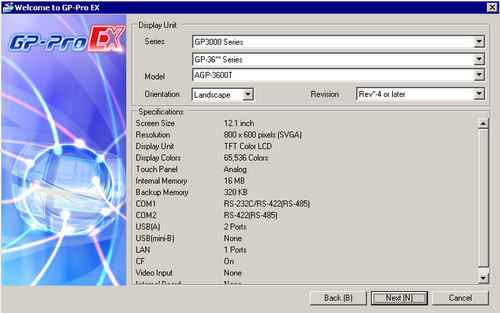
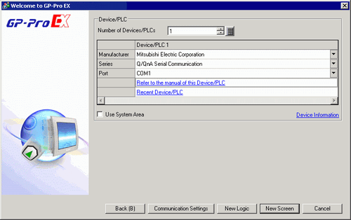
  6. From the [Project (F)] menu, select [Save As (A)].

  7. The [Save As] dialog box appears. Define the storage location and file name and click [Save].

    • Including the path and file extension, the file name can contain up to 256 single-byte or double-byte characters.

    • PRXE format project files cannot be opened in a version before GP-Pro EX Ver.4.09.450. To save as a version before GP-Pro EX Ver.4.09.450, select [Project File (*.prx)].

    • Error checks are automatically performed when projects are saved. If there are problems with the Project Files, the content will be displayed in the [Error Check] Window. By double-clicking the displayed rows, the screen with problems is displayed, so please modify the relevant areas.

    • To verify operation, in the status bar click [Simulation].
      33.1 Settings Menu

Finishing

  1. From the [Project (F)] menu, select [Exit (X)] or click the icon on the top right section of the screen.