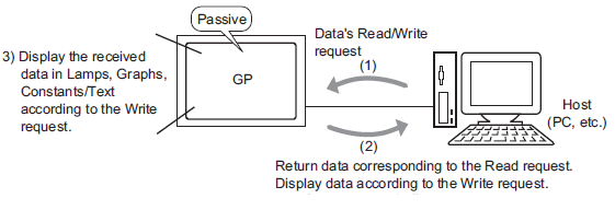
To communicate with a device – such as a PC or microcomputer board (hereafter called the "host") – that does not have its own communication protocol, set up the host to send read or write requests to the display unit. The display unit displays or otherwise operates on the data sent by the host's write request. In response to read requests, the display unit returns stored data to the host.
This communication method that is realized by running the program on the host side is called "Memory Link".
Setup Process
To use the host as a device/PLC unit, configure the [Device/PLC] settings as follows.
Manufacturer Digital Electronics Corporation of Japan
Series Memory Link
For the display unit to get the necessary display data from the host, set an address to reference the data and use it in a Part or script. There are two types of addresses you can reference on the display unit.
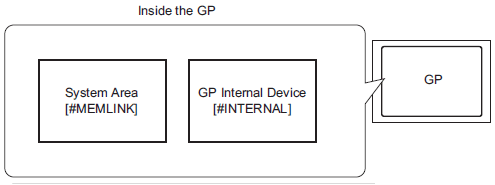
Memory Link System Area Addresses
The System Area is used as the medium for read and write requests to and from the host. The System Area is the Memory Link Method's communication area.
![]() A.1.2 System Area (Memory Link Method Area)
A.1.2 System Area (Memory Link Method Area)
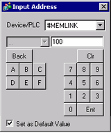
For example, to set a Word Switch address, from [Device/PLC] select [#MEMLINK] and enter the address (for example, "100").
For example, an Input Address screen on a Word Switch.
When using Memory Link communication with the display unit internal device [#INTERNAL], you can only use the [USR] area. For example, you can use the internal device as a temporary storage area when you need to refer to calculated values.
You may use all areas as you like, up to 30,000 Words. The text data storage order is fixed to L/H, no matter what the [Text Data Mode] property is set to in the System Settings window's [Device/PLC] page.
You cannot use the internal device with Memory Link communication.
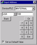
From [Device/PLC], select [#INTERNAL] and enter an address (for example, "USR0100").
For example, an Input Address screen on a [Word Switch].
![]()
When connecting multiple devices, you can use the "LS" area in [#INTERNAL].
![]() 2.4.3 Using Direct Access and Memory Link at the Same Time
2.4.3 Using Direct Access and Memory Link at the Same Time
Data stored in the display unit's internal devices is deleted when the display unit is turned off or enters offline mode, such as when transferring. To retain internal device data, you can copy the User Area's data to backup memory (SRAM).
![]() 5.4.4.3 Display Unit [Mode] - Backup Internal Device
5.4.4.3 Display Unit [Mode] - Backup Internal Device