
Number of Channels
Select the number of graph display data. The setting range is from 1 to 10.
Channel Number
Select the channel to configure. Change to the value of [Number of Channels] to set the control address or source range.
Control Word Address
Set the address that controls the displaying/clearing of the graph.
This can be set to either a PLC address or a display unit's internal device address.
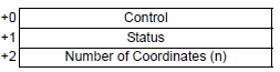
Use a sequence of 3 words from the set address.
![]()
[Control], [Status] and [Number of Coordinates] are all fixed to 16 bit BIN format.
For 32 bit devices, use the bottom 16 bits. Enter [0] for the top 16 bits.
While reading coordinate data, the graph cannot display or clear even if the control address value changes. Change the control address value after the bit 1 in the status address is turned ON.
Control
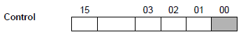
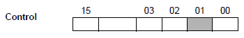
This address' bit 0 and bit 1 control when the graph displays and clears.
When bit 0 is ON (for example, "1" is stored in the address), the graph will be displayed.
When bit 1 is ON (for example, "2" is stored in the address), the displayed graph will be cleared.
When bit 0 and bit 1 are ON (for example, "3" is stored in the address), the graph will temporarily clear and then display again.
![]()
![]()
When the number of data is 0, the operation is as follows.
When Control Address bit 0 is ON and bit 1 is OFF
The graph display of corresponding channels remains the same.
When control address bit 0 and bit 1 are ON
The graph display is cleared but no graph is displayed.
Status
This address stores the drawing status of the graph.
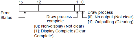
In a graph display, status bit 0 turns ON while clearing the graph.
In a graph display, on completion of clearing the graph, status bit 1 turns ON and bit 0 turns OFF.
Confirm status bit 1 is ON, and turn OFF bit 0 of the Control Address.
Turning OFF bit 0 in the Control Address will also turn OFF bit 1 in the status address.
The error status indicates the following error codes.
Error Code
|
Bit 12 to 15 |
Description |
Introduction |
|---|---|---|
|
0 |
Completed Successfully |
Transfer completed successfully. |
|
1 |
The number of coordinates is 0 |
When the Number of Coordinates is 0. |
|
2 |
Display Range Error |
Occurs when the following is true: 1) [Display Method] = [Display Range] and display ranges are defined using address values. 2) The difference between the upper and lower limits is 0, or the lower limit is greater than the upper limit. When using the auxiliary line, set up when the upper and lower limit widths are less than one. |
|
3 |
Communication error |
A communication (timeout) error occurs when getting coordinates. |
|
4 |
Reserved |
- |
|
: |
|
|
|
15 |
Reserved |
- |
Number of Coordinates
Set the data quantity to store for displaying in a graph. A maximum of 512 coordinates can be set.
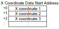
X Coordinate Data Start Address
Set the start address of the address area where X coordinate data is stored. The address area used depends on the device designated in [Start Address] and the [Data Type] settings.
Click the icon ![]() to display the structure of addresses in use.
to display the structure of addresses in use.
For example, when 16 bit device is specified in the address and 16 bit length is set in [Data Type]:
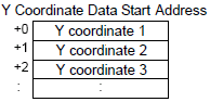
Y Coordinate Data Start Address
Set the start address of the address area where Y coordinate data is stored. The address area used depends on the device designated in [Start Address] and the [Data Type] settings.
Click the icon ![]() to display the structure of addresses in use.
to display the structure of addresses in use.
For example, when 16 bit device is specified in the address and 16 bit length is set in [Data Type]:
X Coordinate/Y Coordinate
Set [Data Type] and [Acquisition Range] for X and Y coordinates.
Data Type
Select the graph display data type from [16 Bit Bin], [16 Bit BCD], [32 Bit Bin], [32 Bit BCD], or [32 Bit Float].
Sign +/-
Set whether graph display data can handle negative numeric data. This can only be set when the [Data Type] is [16 Bit Bin] or [32 Bit Bin].
None
Only positive numeric data will be handled.
2's Complement
Negative numbers are handled with 2's complement.
MSB Sign
Negative numbers are handled with MSB sign.
Min. Value/Max. Value
Select the source data range for data displayed on the XY graph.
The setup range differs depending on the [Data Type] and [Sign +/-].
|
Data Type |
Sign +/- |
Range |
|
16 Bit Bin |
None |
0 to 65535 |
|
2's Complement |
-32768 to 32767 |
|
|
MSB Sign |
-32767 to 32767 |
|
|
32 Bit Bin |
None |
0 to 4294967295 |
|
2's Complement |
-2147483648 to 2147483647 |
|
|
MSB Sign |
-2147483647 to 2147483647 |
|
|
16 Bit BCD |
— |
0 to 9999 |
|
32 Bit BCD |
— |
0 to 99999999 |
|
32 Bit Float |
— |
-9.9e16 to 9.9e16 |
![]()
The corresponding source data values for the X and Y coordinate values are converted as a ratio of 1000 for display in the graph.