![]()
-
Please refer to the Settings Guide for details.
 16.6.1 System Settings [Input Equipment] Settings Guide - Bar Code 1/Bar Code 2
-
For details about the [Copy Memory] script, refer to the following.
22.3 Copying Data in Blocks
Configure settings to store the data from a two-dimensional code reader in the device address of Device/PLC by using an internal device of the display unit.
![]()
Please refer to the Settings Guide for details.
![]() 16.6.1 System Settings [Input Equipment] Settings Guide - Bar Code 1/Bar Code 2
16.6.1 System Settings [Input Equipment] Settings Guide - Bar Code 1/Bar Code 2
For details about the [Copy Memory] script, refer to the following.
![]() 22.3 Copying Data in Blocks
22.3 Copying Data in Blocks
From the [Project] menu, select [System Settings], and click [Input Equipment] to open Input Equipment Settings dialog box.
From the [Type] drop-down list, select [Two-Dimensional Code Reader].
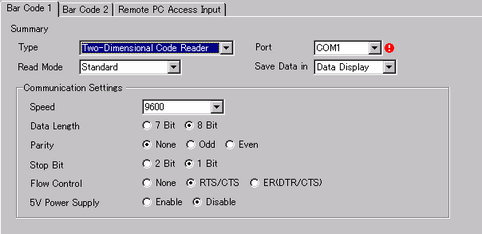
Select the port to connect from [USB/SIO(RS232C)], [USB], or a serial port, such as [COM1].
![]()
If the port is also used for other devices/PLCs, ![]() displays to the right of the [Port] as above.
displays to the right of the [Port] as above.
When using one of the following models, you cannot select [USB/SIO (RS232C)].
IPC Series
SP5000 Series Open Box
LT4000 Series
When using one of the following models, you cannot select [USB].
IPC Series
SP5000 Series Open Box
Set the [Read Mode].
In [Communication Settings], set [Speed], [Data Length], [Parity], [Stop Bit], [Flow Control], and [5V Power Supply].
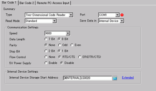
For [Save Data in], select [Internal Device].
From the [Internal Device Storage Start Address], set the start address of the data storage internal device.
![]()
For the internal device's address setting range, refer to the following.
![]() 16.6.1.3 Save Data in
16.6.1.3 Save Data in
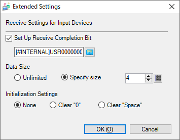
Click [Extended] to configure the [Set Up Receive Completion Bit], [Data Size] and [Initialization Settings]. For [Specify size], set the size of the data to read in bytes.
![]()
If [Set Up Receive Completion Bit] is not set, when data is read continuously the data gets overwritten.
If [Set Up Receive Completion Bit] is set, turn OFF the receive completion bit when input is complete. The display unit will not read code data without turning the read completion bit OFF.
From the [Common Settings (R)] menu, select [Global D-Script] and click [Create].
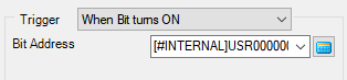
For the [Trigger] select [When Bit turns ON], and specify the bit address that was set in [Set Up Receive Completion Bit] in step 8 as [Bit Address].
Click the [Function] tab, and from the [Built-in Function (Instruction)] select [Memory Operation].
Double-click [Copy Memory], and in the dialog box that follows, define the parameters for the destination address (device address of Device/PLC), source address (internal address), and number of words.
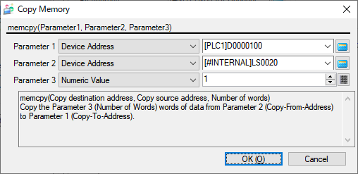
Click [OK]. The program is described in the [Script Expression Area].
Also, from the [Built-in Function(Instruction)] pull-down menu, select [Bit Operation].
Double-click [Clear Bit], and specify the bit address that was set in the [Set Up Receive Completion Bit] field in step 8.
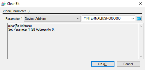
Click [OK].