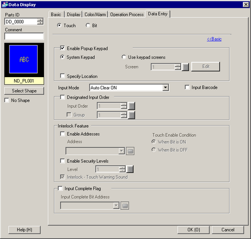
Touch
Enable Popup Keypad
Select to display a pop-up keypad when you touch the Data Display.
Keypad Type
System Keypad
Use the standard keypad registration for GP-Pro EX. Use this in normal cases.
Use keypad screens
Create a user-defined keypad with the Keypad
part. Pre-define the keypad in the Keypad screen. This keypad
allows for customized input.
![]() 15.4.2 Procedure
- Customizing the Keypad Layout / Popup
15.4.2 Procedure
- Customizing the Keypad Layout / Popup
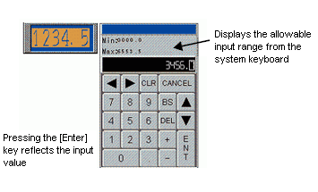
System Keypad
Display the prepared standard keypad registration in GP-Pro EX.
![]()
The range displayed
on the system keypad varies depending on whether or not
the Alarm Settings are being used.
If there are no Alarm Settings, the keypad shows the [Display
Range] minimum and maximum values
If there are Alarm Settings, the keypad shows the [Alarm
Settings] lower and upper limit values
When defining the alarm settings, the upper and lower limits are displayed as the input range.
When the [Scaling Settings] check box is selected, even if no alarm is set up, the upper limit and lower limit are displayed as the input range.
When neither [Alarm Settings] nor [Scaling Settings] are set up, the upper limit and lower limit are displayed as the input range, for the specification data type and the display digit number.
When [Data Type] is set to [32 Bit Bin], the display range and the source range (or the alarm range) during input are not displayed.
When [Data Type] is [32 Bit Float], for cases in which Alarm Settings are not configured, the source range is not displayed.
Use keypad screens
Screen
Set the number of pre-defined custom keypad screen.
Edit
The custom keypad screen specified in the [Screen Number] opens. If no custom keypad is specified, [New Screen] dialog opens.
Specify Location
Used to specify the display position for the pop-up keypad. If selected, the pop-up keypad Display Area can be selected and moved after the Data Display is positioned.
![]()
When you group a Data Display with other parts, you cannot select or move the pop-up keypad display area.
Designated Input Order
When entering data into multiple Data Displays in sequence, select the order in which each display enters the input state.
![]() 14.13 How
Data Input Order Works
14.13 How
Data Input Order Works
Input Order
Select the order, from 1 to 384, in which the Part will enter the input state.
Group
Divide the Data Displays into groups for continuous data input. The cursor will move in turn to each successive Data Display registered in the same group, according to the input order, setting them into the Allow Input state. The Group Number can be from 1 to 10.
Interlock
Define whether or not to use the Address and Security Level when using the Interlock Feature (a feature that enables Touch only when the conditions are satisfied).
![]()
Using Visibility animation, if the object changes from visible to invisible during interlocking, touch operation is still enabled regardless of the visibility/invisibility state, although the switch features will not work.
Use an Address
This function only allows input when the [Address] bit is selected via the [Touch Enable Condition]. Select the check box to use Interlock.
![]() 14.7 Using
Interlock to Prevent Malfunctions
14.7 Using
Interlock to Prevent Malfunctions
Address
Select the bit address that will designate the enable condition, to allow input to be entered. Touch is enabled or disabled depending on the state of this address.
Touch Enable Condition
Select the condition that will enable the part to be touched, to allow input to be entered.
Touch Enable Condition |
Address Status |
Touch Enabled/Disabled |
|---|---|---|
When Bit is ON |
ON |
Touch enabled |
OFF |
Touch disabled |
|
When Bit is OFF |
ON |
Touch disabled |
OFF |
Touch enabled |
![]()
When the Interlock [Touch Enable Condition] is disabled during input, the Data Display will remain in the Allow Input state. Interlock will not work until input is complete.
Use Security Level
Select whether to use the security function for each part. When logged in with a Security Level higher than that set for the part, Touch Operation will be enabled.
Level
Set the Security Level of the part from 1 to 15.
Interlock-Touch Warning Sound
While interlock is on (touch is disabled), on screen touch you can emit a warning sound to indicate the touch operation was ignored.
![]()
To use the touch warning sound, from the [System Settings] [Operation], also turn ON [Interlock - Touch Warning Sound].
Bit
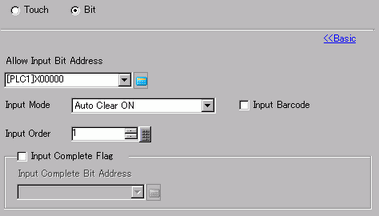
Allow Input Bit Address
When the bit address set here turns ON, the Data Display enters the input state.
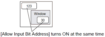
Input Order
Number the Data Displays from 1 to 384 in the order which they will enter the input state if the [Allow Input Bit Address] of multiple Data Displays turns ON at the same time (when a bit address has been registered to multiple Data Displays, or when different bit addresses turn ON at the same time).
![]()
If more than one [Allow Input Bit Address] is turned ON at the same time, the Data Displays will enter the input state according to their [Input Order] settings. If the [Input Order] settings are the same, the input state order will be determined by the order the Data Displays were placed.
If the [Allow Input Bit Address] of Data Displays placed on the Base Screen and Window Screen turn ON at the same time, the Base Screen will have a higher priority for the input state than the Window Screen. When placing Data Displays on both the Base and Window screens, make sure to set a different [Allow Input Bit Address] for each.
Input Mode
Auto Clear OFF
New data will build on previously input data. Pressing [CLR] on the keypad clears the value.
Auto Clear ON
The first key pressed (except cursor moves, [ENT], [DEL], or [BS]) will clear the previously input text data.
Auto Clear ON + Input Check
When using barcode input, performs automatic clear and checks whether the number of input digits coincides with the [Display Characters].
If the number of display digits is less than the [Display Characters] total, the data will not be written to the word address.
![]()
When [Zero Suppress]
is not selected, data is padded with zeros to fill in
missing digits to match the number of display digits.
For details on Zero Suppress, refer to the following.
![]() 14.11.1.6 Numeric
Display - Display/Extended
14.11.1.6 Numeric
Display - Display/Extended
When the [Decimal
Places] is set, the number of digits you need to input
is "Total Display Digits - Decimal Places".
If you input an integer value, the right of the decimal
point is populated with 0.
For example, if the Total Display Digits is 6 and the Decimal
Places is 2, you can enter 4 digit integer values.
![]()
Input Barcode
A setting that allows input from a barcode reader.
![]() 16.2.1 Procedure
- Connecting a Bar Code Reader
16.2.1 Procedure
- Connecting a Bar Code Reader
Input Complete Flag
Detects and notifies you when input has been completed.
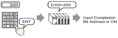
Input Complete Bit Address
Sets the bit address that will turn ON when input has been completed.
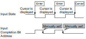
![]()
This address is not turned OFF automatically. After confirming it is ON, turn OFF.